Click Thumbnails For Larger Image
© vk6.org
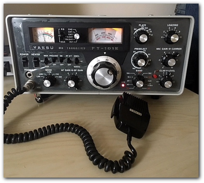
Introducing my FT101E transceiver which I purchased around 40years ago and this "baby" still looks like new with the plastic film on the front panel.
The radio has the same specification as the FT101F (last in the line) featuring HF bands 160m to 10m, 11m Citizens Band, noise blanker, speech processor and built in DC Inverter for 12V operation.
The transmit power capability is SSB 260 watts, CW 180 watts , AM 80 watts utilising a pair of rugged 6JS6C Toshiba TV sweep tubes.
The radio still works well and is my daily "user" but it has not been without issues, after being boxed and stored for about 15 years while overseas it was a little reluctant to come back to life after it's long sleep. Many of the elcos' had dried out and soon went short circuit resulting in a burned out mains transformer which I had to source from the USA. All the recognised modifications have been carried out including a brand new pair of Toshiba Green Stripe Tubes.
I love this baby - it has been a companion for 40 years and I would not wish to swap any modern toy radios.

 |
Front Panel Removal |
|
 |
Pilot Lamp Replacement |
|
 |
Removing Mechanical Drive Shafts |
|
 |
FT101E |
|
 |
Inspecting the VFO |
|
 |
Front Panel and VFO Removed |
|
 |
Top View |
|
 |
Bottom View |
|
 |
FT101E |
|
 |
VFO Re - Installed |
|
 |
Mains Transformer Compartment |
|
 |
FT101E |
|
 |
Removing the "Jones" Plug |
|
 |
Top View of the Transformer |
|
 |
Removing the Rectifier Board |
|
 |
Disconnecting the Transformer |
|
 |
Finally "It's Out" |
|
 |
Burn Up on Base ot the Driver Tube |
|
 |
Power Regulator Board |
|
 |
Rear View after Reassebbly |
|
Some Pictures taken during the stripdown for the Transformer replacement and modifications. Click the thumbnails below for a larger image.