G4AXP Top Band Magnetic Loop Antenna - As I said in my earlier narrative, I am no technical expert in these matters so what you see laid out is my "layman's" interpretation of my endeavours.
Following on from my efforts to produce a low cost, lightweight Magnetic Loop Antenna for 80M, 60M and 40M using low cost materials,
I was keen to find out if a "SML" would perform on Top Band. The main conductor is formed from MDPE irrigation pipe 25mm in diameter and shrouded with 50mm wide adhesive copper tape.
The determining issues being the size of the loop and the value of capacitance required to tune down to 1.9mhz and below.
To cover Top Band a loop using a conductor of approximately I inch, (25mm) in diameter and tuned with a 500pf capacitor would need to be about 45 feet in length which would equate to a loop diameter of over 14 feet. Forming the conductor into two turns results in a loop just over 7 feet in diameter. Theory suggests that the size primary loop should be approximately 1/5 the diameter of the secondary loop for maximum power transfer and a good impedance match to 50 ohm, with 2 turns and a conductor length of 45 feet, I have increased the diameter to 26 inches to achieve a good match.
In researching the effectiveness of multi-turn loops, much is written about the proximity effects of two turns and that such loops may only be marginally more efficient than a one turn loop of the same size and exhibit a similar restricted bandwidth.
Whereas it is quite possible to use smaller diameter loops on the higher bands, the capacitance required for 160 meters at 1.9mhz, using a seven foot diameter loop is greater than 1000pf and efficiency just 2% compared to an efficiency if 15% for the large conductor.
Because of the high voltage across the tuning capacitor, around 5KV, it was important to acquire a Vacuum Variable which works well and as it is around 30 turns across it's value, this makes the fine tuning far less critical than a regular air spaced unit.
The loop's two turns are 6 inches (16CM) apart which hopefully reduces the proximity effect if this was ever to be an issue.
Bandwidth on this type of antenna is restrictive assuming you are able to achieve the required "Q". Typical bandwidth on 160m is 1.8kc/s which calls for precise tuning. Using an air-spaced variable capacitor is restrictive as it only allows for a half turn from minimum to maximum capacitance, however a Vacuum Variable typically has around 30 turns through it's capacitance range allowing for broader selectivity.
A simple and low-cost method of tuning is with a small DC motor offering a 3-RPM drive being coupled to the Vac-Cap by a 6mm plastic drive shaft. This easily allows for the critical tuning required. I have added a Reversible-Speed Controller which allows for forward/reverse and stop giving control of the motor speed.

© vk6.org
Materials
Click any image for a full size view
The Materials used are identical to those used to form the single turn loop as described earlier:
|
|
|
|
||||||||
|
|
|
|


")
Assembly Details
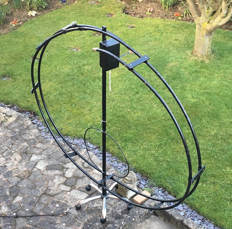
The main conductor (45 feet), was made in two sections using a pipe joining connector. The adhesive copper foil is applied length-wise in two strips along each side of the sections of plastic pipe. PVC tape was spiral wrapped over the foil to form a protective shroud.
The conductor is then formed into two turns while laying flat on the ground giving a diameter of around 7 feet.
Eight plastic spacers around 8 inches wide are fitted between the two loop turns to maintain a unified distance of 6 inches and add to the rigidity, more can be used if necessary. Plastic pipe clips are used to hold the pipe in place..
The loop is mounted on a wooden support measuring: 1.25 inches x 0.75 inches x 7feet - which holds the antenna firmly. This wooden mast is is tightly wrapped with PVC tape for protection from the elements.
The Vacuum Capacitor is housed in a polystyrene enclosure which is covered in thick PVC for added protection.
The Capacitor was originally mounted at the bottom of the assembly because of the weight factor however, various articles on the subject suggest that the top is the best position, I cannot determine any difference between these two positions.
First Impression
Early results with the loop standing within the house were very favourable. During assembly and initial testing the loop was positioned in a spare upstairs bedroom and the overall results were good.
I cannot determine any improvement in the transmitted signal with the Loop set outside other than the fact that the residual band noise is far lower on receive. The band noise on 160M is drastically reduced on receive using the loop. The typical daytime noise floor on the wire antenna at this QTH is S-5 and this reduces to S-1 with the loop. The receive performance is improved too, during a recent daytime QSO I was receiving a semi-local station 15db stronger with the loop while still maintaining S-1 background under no signal conditions.
Transmitted Signal reports are up on the regular "Inverted L" antenna which is at around 35' off the ground which is the yardstick.
Directionality is acute both with local stations and those up to 1000miles and I have had a number of SSB contacts within Europe with S9 reports.
More recently, I was called 1950kc/s by a station on near Frankfurt at 4pm and received a 5-8 signal report.
Eric, G3IMX called me during April at around 3.30pm in the afternoon and gave me a 5.8 report, good for daytime conditions.
Tests on the 80M band have also show really good results with up to 15db reduction in band noise and I have had many contacts around the UK with just 100W.
Conclusion
The loop will never match a dipole at 60 feet but size noise and directionality are a definite bonus
I am now certain that the loop's performance is not so good down at patio level due to ground absorption and really needs to be raised by a few feet to overcome this issue.
The flexibility of the Plastic Tubing would make it possible to transport the Loop Antenna for portable operation.
Will a 2 Turn Small Magnetic Loop Work on Top Band, 160M - Let's Find Out!

|
|


Click any image for a full size view
The images show band noise on 160 meters at mid-morning significantly reduced when switching to the Loop Antenna and a report on on a contact with ON2PCO near Maastrict on Feb 23 confirming the increase in signal on the loop.
|

|